Trash Can Mechanism
Project: Design and model a mechanism to move a tray around a trash can.
Duration: 1 week in April 2022.
Objective: Design a mechanism to take a tray from the top of a trash bin around to an opening on the side of the bin. The tray had to remain roughly horizontal until it reached the opening on the side of the bin so trash did not fall off. The tray could not hit the trash bin while moving to the opening. The tray had to start horizontally 15 inches from the corner of the bin and end vertically 15 inches down from the corner of the bin. The tray was 35 inches long and 5 inches thick. Pivot points had to be on the side of the trash can.
Approach: To achieve this motion ideally 2 points on the tray would follow identical paths around the bin, keeping the tray horizontal, until at the very they deviated to rotate the tray. To do this the idea was to have one point on the tray follow a strictly circular path, while another point on the tray followed a path generated by a 4 bar linkage. Using a 4 bar linkage it is possible to generate a path that is roughly circular until an inflection point where it shoots off on a different trajectory. This sort of path combined with a circular path could keep the tray horizontal until the inflection point where it then quickly rotated the tray. Math Illustrations was used to create the necessary circular path. Then by putting a trace on a 4 bar linkage, the location of the trace and relative length of the links could be varied until the desired path was obtained. An assembly was then created in SolidWorks using the link dimensions determined in Math Illustrations.
Challenges: Since the 4 bar linkage path wasn't perfectly circular, a small slot was needed on the tray to connect it to the 4 bar linkage. This left the model under constrained, and SolidWorks was unable to solve the motion of the tray. Additionally, due to the added degree of freedom there was no single link that could be used to drive the mechanism while achieving the desired tray motion.
Solutions: To allow the mechanism to be driven by only one link, two additional links were added,
connecting to the tray at a third point to drive the mechanism. In a realistic setting this could produce reliable tray motion while the model is under constrained due to the friction in linkage components, that cause them to "follow behind" the driving link. To model this in SolidWorks, rotational dampers were added to the non driving links. Additionally, the slot was modeled using contact forces between components. This gave SolidWorks enough information to solve the motion of the linkage.
Results: The desired motion was achieved using only one driving link under realistically possible conditions. However, no consideration was given to interference between the mechanism links. To implement this mechanism in reality, further design would be needed to make sure the the links wouldn't interfere during the motion of the mechanism.
Future Improvements: The paths used to control the motion of the tray were primarily generated using graphical methods. Using more elegant numerical methods, it might be possible to achieve the same motion without the need for a slot. This would allow the model to be properly constrained and eliminate the need for the two additional links to drive the motion.

Design requirements.
SolidWorks animation of the mechanism taking the tray to the side opening and then returning it to the original position.

Paths generated using Math Illustrations.
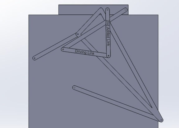
Image of the mechanism with with the driving link and the other added link labeled.